
The DC-AC motor forward and reverse control system realized by C31-04R under Ebyte Company, the system can be controlled by local buttons, or can be connected to the cloud server through the 4G network and then controlled through the mobile APP (using Alibaba Cloud's "cloud" Smart”), and can also be controlled within 4Km through the remote control.
Relay on-load analysis
C31-04R uses a power relay with normally open contacts (normal temperature 30A@277VAC, resistive), normally closed contacts (normal temperature 15A@277VAC, resistive), withstand voltage level (medium withstand voltage between coil and contacts 2.5KVAC 1min, 1500VAC 1min between disconnecting contacts), the detailed parameters of the relay are shown in the following figure:

Contact Load Description
The load that the relay contacts can bear, in addition to confirming the size of the load, it is also necessary to confirm the type of the load. Different load types have different inrush current and steady-state values, as shown in the following table:
Type of load Inrush current
Resistive load 1 times the steady state current
Motor load 5~10 times of steady state current
Capacitive load 20~40 times of steady state current
Transformer load 5~15 times of steady state current
Solenoid load 10~20 times of steady state current
Incandescent lamp load 10 to 15 times the steady state current
Mercury lamp load Approx. 3 times the steady state current
Sodium lamp load 1~3 times of steady state current
Considering the above descriptions, low-power DC motors (below DC 28V) are not recommended to be used for a long time in the range of 3~6A. When the DC power is turned off, the arc is not easy to be extinguished. Therefore, special equipment is required to disconnect the DC power (such as Chint's NCZ2 series DC contactors). contactor), the AC motor is recommended to be used with a contactor.
Non-professionals are prohibited from wiring, and overload and overvoltage use are strictly prohibited to avoid electric shock.
Forward and reverse circuit analysis of DC motor
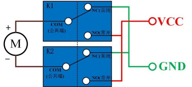
When a forward voltage is applied to both ends of a DC motor, the motor rotates forward, and when a reverse voltage is applied, the motor rotates reversely. Using this characteristic of the DC motor, the control of the forward and reverse rotation of the DC motor can be realized by controlling the normally open and normally closed contacts of the relay.
Scenario 1: When both coils of K1 and K2 are powered off, the common terminal (COM) of the relays K1 and K2 is connected to the normally closed (NC) contact, and the common terminal (COM) and the normally open (NC) contact are disconnected. The two wires of the motor are only connected to GND, and the circuit does not form a loop, and the motor will not rotate at this time;
Scenario 2: The K1 relay coil is turned on and the K2 relay coil is disconnected, the common terminal (COM) of the K1 relay is connected to the normally open (NO) contact, and the common terminal (COM) of the K2 relay is connected to the normally closed (NC) contact. When the current flows from the positive terminal of the power supply through the normally open (NO) contact of the K1 relay to the common terminal (COM) contact of the K1 relay, then flows through the positive terminal of the motor, and flows from the negative terminal of the motor through the common terminal of the K2 relay. terminal (COM), and then flows through the normally closed (NC) contact of the K2 relay to return to the negative pole of the power supply. At this time, the motor is conducting forward, that is, the motor is rotating forward;
Scenario 3: The K1 relay coil is disconnected and the K2 relay coil is turned on, the common terminal (COM) of the K1 relay is connected to the normally closed (NC) contact, and the common terminal (COM) of the K2 relay is connected to the normally open (NO) contact. When the current flows from the positive terminal of the power supply through the normally open (NO) contact of the K2 relay to the common terminal (COM) contact of the K2 relay, then flows through the negative terminal of the motor, and flows from the positive terminal of the motor through the common terminal of the K1 relay. terminal (COM), and then flows through the normally closed (NC) contact of the K1 relay to return to the negative pole of the power supply. At this time, the motor conducts reversely, that is, the motor reverses;
Scenario 4: When both coils of K1 and K2 are turned on, the common terminal (COM) of the relays K1 and K2 is connected to the normally open (NO) contact, and the common terminal (COM) and the normally open (NC) contact are disconnected. The two wires of the motor are only connected to VCC, the circuit does not form a loop, and the motor will not rotate;
Forward and reverse circuit analysis of AC motor
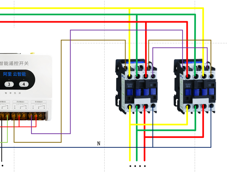
The AC contactor mentioned in this article uses a contactor whose coil rated voltage is AC 220V and the auxiliary contact is a normally closed contact. Therefore, it is necessary to introduce a neutral line (N) separately. If an AC 380V contactor is used, just replace the neutral line with L1 Or L2, but the auxiliary contact must be normally closed to realize the forward and reverse rotation of the three-phase motor according to the circuit diagram shown in this article.
By exchanging any two phases of the three-phase AC motor, the opposite steering to the original steering can be realized.
Scenario 1: The switch output 3 and switch input 4 do not work, then the two contactor coils are not closed, the three-phase electricity is not conducted, and the motor does not work;
Scenario 2: Switch output 3 is output, the KM1 contactor is closed, the KM2 contactor is not closed, the motor is connected to the positive line sequence voltage to realize the forward rotation of the motor, and then click switch 4 to output switch 4. Since KM1 is closed, KM1's When the auxiliary contact is disconnected, the KM2 contactor cannot be closed, so as to realize the control and protection of the forward and reverse rotation of the motor.
Therefore, the forward and reverse rotation control system preferably switches the forward and reverse rotation of the motor in a stopped state.


