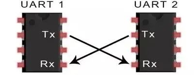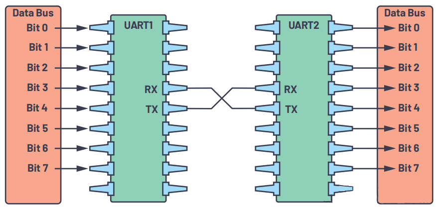

UART is a commonly used serial communication protocol(Related article : RS232/RS485 serial port communication introduction) that is widely used in communication between microcontrollers or various embedded devices. This article will introduce in detail the basic principles, working modes, baud rate calculation and common usage methods of UART communication to help people with certain microcontroller development capabilities better understand and apply UART communication.
Get to this page quickly 1.Data queue (Queue) sending and receiving |
Basic principles of UART communication
UART communication is an asynchronous serial communication method. Its basic principle is to transmit binary data bits through data lines. The UART communication system is mainly composed of two parts: the sending end and the receiving end, and data is transmitted between them through data lines. The sending end converts the data to be sent into parallel signals, then converts the parallel signals into serial signals through the driving circuit, and sends the serial signals to the data line through the sending circuit. The receiving end restores the signal on the data line to a parallel signal through the receiving circuit, and then converts the parallel signal into the original data bit through the decoding circuit.

Related Article :
China SPI/SOC/UART Module Company, Serial Wireless Module factory
SPI/SOC/UART TRIAL MODULES, Exploration range find your customized design. We provide good quality SPI/SOC/UART Modules from China and wholesale Serial Wireless modules
online.CDEBYTE is committed to helping the development of IoT
Intelligence and automation more powerfully every day, improving
resource utilization. We're empowering innovation to help make IoT truly
your own.You can trust CDEBYTE with your next serial wireless project.
UART communication adopts asynchronous communication method, that is, data transmission is carried out through data lines between the sending end and the receiving end. In asynchronous communication, the sender and receiver do not need to be active at the same time. Instead, the start and stop bits are used to identify the start and end of the data frame. Specifically, when the sending end generates the start bit, it sends one data bit; then it waits for the starting bit of the receiving end. If the start bit is received, it continues to send the next data bit; if the start bit is not received, then It is considered that the data frame transmission failed. Similarly, when the receiving end generates a stop bit, it sends a check bit; then it waits for the stop bit from the sending end. If the stop bit is received, the data frame transmission is considered successful.

The baud rate represents the number of bits of binary data transmitted through the line per unit time, usually expressed in bps (bits per second). For example, if the baud rate is 9600bps, 9600 bits of data can be transmitted per second.
The baud rate of serial port transmission data is generated by the clock system of the microcontroller, so it has a mathematical relationship with the system clock of the microcontroller.
Baud rate = (16 * clock frequency) / (32 * sampling time) + (1 * clock frequency) / (32 * sampling time) - (1 * clock frequency) / (64 * sampling time)
Among them, the sampling time refers to the time interval from the last starting bit to the current starting bit. For example, if the sampling time is 10ns, the baud rate is 9600bps.
Common baud rates are 2400, 4800, 9600, 19200, 38400, 57600, 115200... They are all integer multiples of 2400, so different baud rates can be generated through frequency dividers. Although today's microcontrollers have different frequencies, the common ones are 32MHz, 48MHz and 144MHz. Usually they have an external system clock that provides a basic clock frequency (such as 1MHz) for the peripheral devices of the microcontroller. The UART baud rate is also generated from this clock. Generate clock signal.
It should be noted that in actual use, the clock frequency may be affected by some factors, such as crystal oscillator drift, power supply noise, etc. Therefore, in order to ensure the accuracy and reliability of data transmission, it is recommended to use an external crystal oscillator or clock generator and calibrate and compensate it when designing a UART communication system.
In UART asynchronous communication, the stop bit is used to indicate the end of the data frame. The stop bit can be 1 or 2 bits. When the stop bit is 1 bit, an extra time interval is added after each data byte to compensate for errors caused by clock jitter and other factors. For example, if the baud rate is 9600bps, the time interval between each byte is 4ms, so the time interval between each stop bit is 4ms / 8 = 0.5ms.
When the stop bit is 2 bits, two additional time intervals are added after each data byte, that is, the time interval for each byte is 4ms / (8 + 4) = 0.3125ms. This mode is suitable for data transmission scenarios that require higher accuracy.
Parity checking is a commonly used error detection method to detect errors and losses during data transmission. In UART communication, the accuracy and reliability of data transmission can be improved by setting the parity bit.
It should be noted that the parity bit can only detect errors and losses during data transmission, but cannot guarantee the integrity and correctness of the data. Therefore, when using UART communication, other measures need to be taken to ensure the correctness and reliability of data transmission.
UART polling transceiver and interrupt transceiver
As we mentioned before, UART communication is to split a byte of data into several bits, and then send them one by one. When a byte of data is sent to the UART transmitter, the byte is converted into bits. After the UART sends this byte, a stop bit is generated. At this time, the UART transmitter is idle and can continue to send the next byte. . Usually the UART transmitter will generate an idle state after sending a byte. Polling transmission is to wait for this idle state and send the next byte.
The same is true for UART reception. When the UART receiver finishes receiving a byte and receives the stop bit signal, it will save the just received data to the UART data register of the microcontroller and generate a receive flag bit. Polling the flag bit will This byte of data can be received.
However, in single-chip microcomputer systems, there are often more than just UART transceiver applications, and interrupt transceivers must be used. Usually the UART transceiver of the microcontroller has RX reception interrupt and TX completion interrupt. When interrupting transmission, the UART transmitter is in idle state. At this time, the first byte is written into the transmitter. After the byte is transmitted, a TX completion interrupt is generated. The subsequent bytes are filled in the service function of the TX completion interrupt. And generate the next interrupt, and finally until all the bytes that need to be transmitted are transmitted. When interrupting reception, the UART receiver will generate an RX receive interrupt after receiving a byte. The received byte is read in the RX receive interrupt service function. The received byte is read during each interrupt.

UART transceiver with data cache
In many microcontroller systems, interface functions such as UART Read and UART Write are provided. Some advanced microcontrollers even have callback functions such as UART Read Callback and UART Write Callback to send and receive data. Usually the data processing capabilities of many microcontrollers are much faster than UART communication, so microcontroller systems that use the above interface functions use data cache to assist UART transceiver. Common UART sending and receiving methods include the following:
1.Data queue (Queue) sending and receiving
This method is suitable for most microcontrollers, as long as there are interrupts. When using UART Write to send data, the data is not written directly to the UART transmitter, but is placed in a ring buffer. Then read the ring buffer in the UART TX transmission complete interrupt service function and send the read byte to the UART transmitter, and then wait for the TX transmission completion interrupt service function to be executed again to send the next byte until the ring buffer is until the data in the area is sent out. A ring buffer usually has a variable that marks the head and tail. As long as the variable values of the head and tail are not equal, it means that the buffer has data. When using UART Read to receive data, the data is not obtained directly from the UART receiver, but from the ring buffer. In the UART RX interrupt service function, the bytes received by the UART receiver are sent into the ring buffer. The data obtained when the microcontroller executes UART Read is the data in the ring buffer. This ensures that the microcontroller program does not have to wait for the UART receiver. .
The advantage of this design is that it can effectively process real-time data and avoid data loss. However, if the Queue size is set improperly, data overflow may occur. Therefore, we need to set the Queue size reasonably according to the actual application scenario.
2.UART transceiver with hardware FIFO
Many advanced microcontrollers use hardware FIFO for UART transceiver. A microcontroller without hardware FIFO will execute an interrupt function every time it sends and receives data. When communicating at a high baud rate, the microcontroller will frequently enter interrupts, thus affecting the processing of the main task of the microcontroller. The hardware FIFO can alleviate this contradiction. For example, the UART FIFO of a single-chip microcomputer is 16 bytes. When sending data, the single-chip computer can transmit up to 16 bytes of data at a time. The UART TX transmission completion interrupt will not be generated until the 16-byte data is sent. When receiving data, there are usually "half-full" interrupts and "timeout" interrupts, that is, the number of bytes in the receiving FIFO exceeds 8 bytes, or the receiving FIFO is not empty but no new bytes are received for more than 1 byte. data, generating a UART RX receive interrupt. Usually UART with hardware FIFO is used in combination with data queue, and the transmission efficiency is higher under high baud rate communication.
DMA (Direct Memory Access) is a technology that can directly map a certain storage area of the computer to the memory address space, thereby achieving unified access to memory and other peripherals. When the UART receives data, the data will be written directly into the DMA-controlled memory area and then trigger an interrupt. In the interrupt service routine, we can retrieve the data from the DMA-controlled memory area, perform necessary processing, and then send it out through UART.
Using DMA for UART transmission is particularly helpful for transmitting multiple consecutive pieces of data, such as the UART Read Callback and UART Write Callback callback functions mentioned earlier. When sending multiple data streams continuously, the data streams can be placed in multiple different buffers of the microcontroller, and then the DMA directly points to the buffer address. After the DMA transmission is completed, a UART Write Callback is generated, and then the DMA is pointed down in the UART Write Callback. A buffer address. When receiving data, you can also reserve a receive buffer. The data transferred by DMA is transferred to the buffer. When the transfer is full, a UART Read Callback is generated and points to the next receive buffer. At the same time, the microcontroller main program can process the buffer that has received full data. area content.
This article introduces in detail the basic principles of UART communication, baud rate calculation, working mode and common usage methods, helping people with certain microcontroller development capabilities to better understand and apply UART communication. Mastering UART communication technology can bring great convenience to the design and application of microcontroller control systems.
Recommended articles:
How to choose serial communication?
Common issues about Serial Communication
Detailed explanation of SPI communication protocol
- Summary of ZigBee Protocol: ZigBee 3.0 VS ZigBee Pro
- How to reduce the impact of common mode interference on communication systems?
- Global Attention: Groundbreaking Discovery of Room-Temperature Superconductivity
- Edge Computing Overview
- NB144 Serial Server Simulation Communication, Huawei Cloud MQTT Communication Protocol Access Guide


