
[Chip]:SX1268
[Frequency]:410.125~493.125MHz
[Transmit power]:30dBm
[Communication distance]:10km
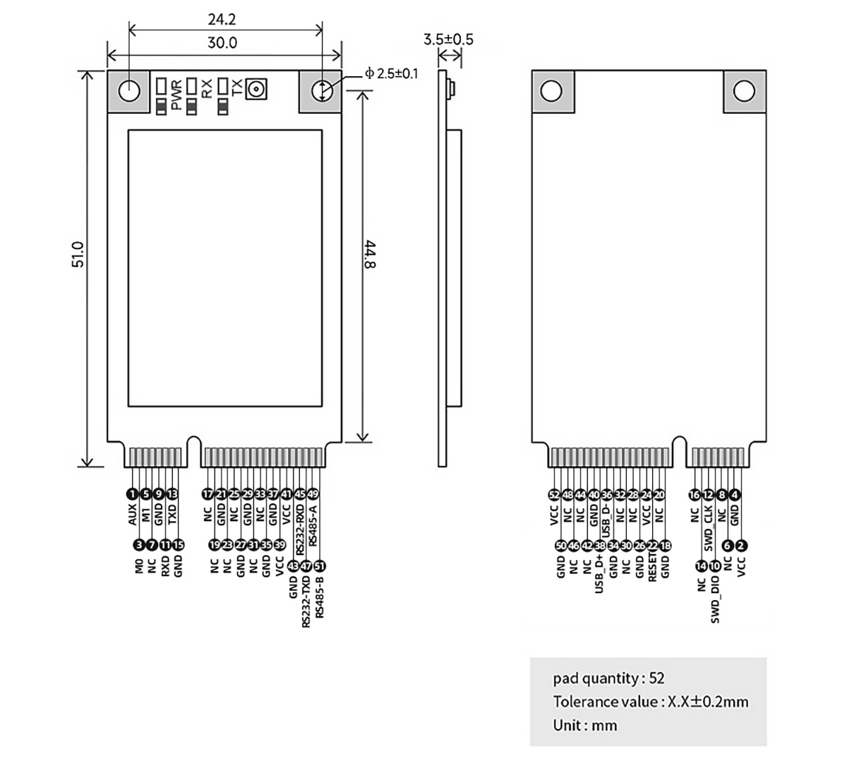
[Size]:30 * 51 mm
[Introduction]:E22-400T30E is a new generation of LoRa wireless module. It is designed based on the wireless serial port module (UART) of SEMTECH's RF chip and the original SX1268 chip scheme of SEMTECH. It has a variety of transmission methods, works in the (410.125 ~ 493.125MHz) frequency band (default 433.125MHz), LoRa spread spectrum technology, TTL level output, compatible with 3.3V and 5V IO port voltage.

| Pin number | Pin name | Pin Orientation | Pin usage |
| 1 | AUX | Output | It is used to indicate the working state of the module; the user wakes up the external MCU, and outputs a low level during the power-on self-test initialization; (can be left floating) |
| 2 | VCC | Enter | Power input 5.0V |
| 3 | M0 | Input (very weak pull-up) | Cooperate with M1 to determine the 4 working modes of the module(can not be suspended, if not used, it can be grounded) |
| 4 | GND | - | Power reference ground |
| 5 | M1 | Input (very weak pull-up) | Cooperate with M0 to determine the 4 working modes of the module(can not be suspended, if not used, it can be grounded). |
| 6 | NC | - | - |
| 7 | NC | - | - |
| 8 | NC | - | - |
| 9 | GND | - | Power reference ground |
| 10 | SWD_DIO | Input/Output | Program download data interface (the module needs to be reset or chip erased before SWD programming). |
| 11 | RXD | enter | TTL serial port input, connect to external TXD output pin |
| 12 | SWD_CLK | Input/Output | Program download clock interface (the module needs to be reset or chip erased before SWD programming) |
| 13 | TXD | output | TTL serial output, connect to external RXD input pin |
| 14 | NC | - | NC pin, this pin needs to be left floating (for subsequent expansion) |
| 15 | GND | - | Power reference ground |
| 16 | NC | - | - |
| 17 | NC | - | - |
| 18 | GND | - | Power reference ground |
| 19 | NC | - | - |
| 20 | NC | - | Power reference ground |
| 21 | GND | - | Power reference ground |
| 22 | RESET | enter | Input high level module enters hardware reset state, input low level module returns to normal working state, this function is used for reset operation in emergency |
| 23 | NC | - | - |
| 24 | VCC | enter | Power input 5.0V |
| 25 | NC | - | - |
| 26 | GND | - | Power reference ground |
| 27 | GND | - | Power reference ground |
| 28 | NC | - | - |
| 29 | GND | - | Power reference ground |
| 30 | NC | - | - |
| 31 | NC | - | - |
| 32 | NC | - | - |
| 33 | NC | - | - |
| 34 | GND | - | Power reference ground |
| 35 | GND | - | Power reference ground |
| 36 | USB_D- | Input / Output | D- for external USB devices |
| 37 | GND | - | Power reference ground |
| 38 | USB_D+ | Input / Output | D+ for external USB devices |
| 39 | VCC | Input | Power input 5.0V |
| 40 | GND | - | Power reference ground |
| 41 | VCC | Input | Power input 5.0V |
| 42 | NC | - | - |
| 43 | GND | - | Power reference ground |
| 44 | NC | - | - |
| 45 | RS232_RXD | Input | External TXD of other RS232 devices |
| 46 | NC | - | - |
| 47 | RS232_TXD | Output | External TXD of other RS232 devices |
| 48 | NC | - | - |
| 49 | RS485_A | Input / Output | Connect to the A terminal of other RS485 devices |
| 50 | GND | - | Power reference ground |
| 51 | RS485_B | Input / Output | Connect to the B terminal of other RS485 devices |
| 52 | VCC | Input | Power input 5.0V |


