


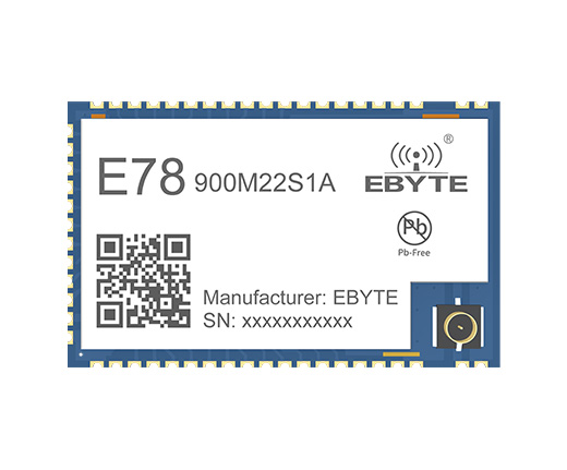
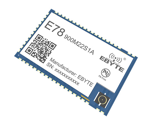
LoRa Receiver ASR6505 868MHz 915MHz Wireless RF Transceiver SOC Module IPEX Stamp Hole LoRaWAN IoT Smart Home
[IC]:ASR6505
[Frequency]:850~925MHz
[Power]:22dBm
[Distance]:5.5km
[Size]:26* 16*2.8mm
[Introduction]:The E78 series products are radio frequency transceiver modules with multiple frequency bands designed and produced by Ebyte, with long communication distance and extremely low current consumption in low power consumption mode. This module is a small-volume patch type (pin spacing 1.1mm).
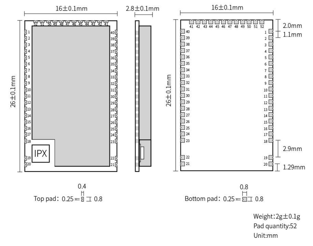
| No. | Name | Direction | Function |
|---|---|---|---|
| 1 | GND | - | Ground wire, connected to the power reference ground |
| 2 | LCD-SEG10 | Input/output | MCU GPIO |
| 3 | LCD-SEG11 | Input/output | MCU GPIO |
| 4 | LCD-SEG12 | Input/output | MCU GPIO |
| 5 | LCD-SEG13 | Input/output | MCU GPIO |
| 6 | LCD-SEG14 | Input/output | MCU GPIO |
| 7 | LCD-SEG15 | Input/output | MCU GPIO |
| 8 | LCD-SEG16 | Input/output | MCU GPIO |
| 9 | LCD-SEG17 | Input/output | MCU GPIO |
| 10 | I2C-SDA | Input/output | I2C-SDApin |
| 11 | I2C-SCL | Input/output | I2C-SCL pin |
| 12 | ADC-IN0 | Input | ADC input pin |
| 13 | ADC-IN1 | Input | ADC input pin |
| 14 | GPIO2 | Input/output | MCU GPIO |
| 15 | GPIO3 | Input/output | MCU GPIO |
| 16 | GPIO4 | Input/output | MCU GPIO |
| 17 | ADC_IN2 | Input | ADC input pin |
| 18 | GND | - | Ground wire, connected to the power reference ground |
| 19 | ANT | output | Antenna interface, stamp hole (50 ohm characteristic impedance) |
| 20~23 | GND | - | Ground wire, connected to the power reference ground |
| 24 | SPI-NSS | Input | SPI select pin, can select external SPI |
| 25 | SPI-SCK | Input | SPI-SCK pin, can be used as external SPI |
| 26 | SPI_MISO | output | SPI_MISO pin, can be used as external SPI |
| 27 | SPI_MOSI | Input | SPI MOSI pin, can be used as external SPI |
| 28 | LCD-SEG1 | - | MCU GPIO |
| 29 | LCD-SEG2 | Input/output | MCU GPIO |
| 30 | SWIM | Input/output | Program burning pin |
| 31 | NRST | Input | External reset pin |
| 32 | LCD-COM0 | Input/output | MCU GPIO |
| 33 | LCD-COM1 | Input/output | MCU GPIO |
| 34 | LCD-COM2 | Input/output | MCU GPIO |
| 35 | VREFP | Input | ADC reference voltage input |
| 36 | UART1-RX | Input | UART1-RX pin |
| 37 | UART1-TX | output | UART1-TX pin |
| 38 | VLCD | Input | VLCD pin |
| 39 | LCD-SEG0 | Input/output | MCU GPIO |
| 40 | GND | - | Ground wire, connected to the power reference ground |
| 41 | LCD-SEG3 | Input/output | MCU GPIO |
| 42 | LCD-COM3 | Input/output | MCU GPIO |
| 43 | LCD-SEG4 | Input/output | MCU GPIO |
| 44 | LCD-SEG5 | Input/output | MCU GPIO |
| 45 | UART0-RX | Input | UART0-RX pin |
| 46 | UART0-TX | output | UART0-TX pin |
| 47 | LCD-SEG6 | Input/output | MCU GPIO |
| 48 | LCD-SEG7 | Input/output | MCU GPIO |
| 49 | LCD-SEG8 | Input/output | MCU GPIO |
| 50 | LCD-SEG9 | Input/output | MCU GPIO |
| 51 | VCC | - | Power supply, range 2.5V ~ 3.7V (recommended to add external ceramic filter capacitor) |
| 52 | GND | - | Ground wire, connected to the power reference ground |