


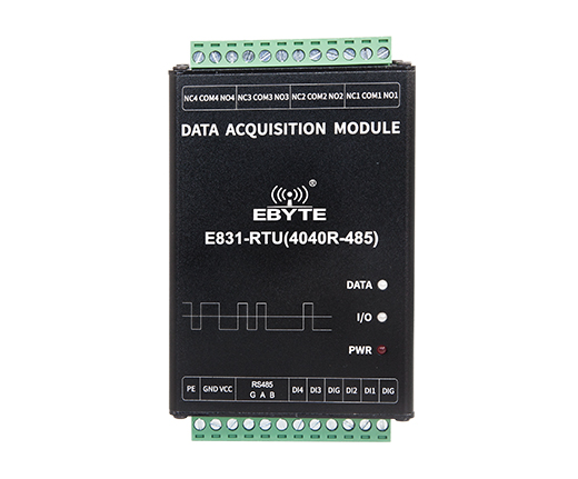
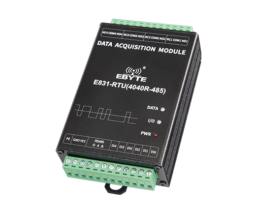
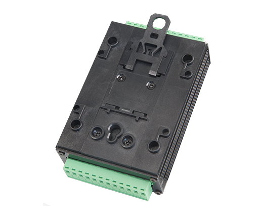
E831-RTU(4040R-485) Digital 8-way IO controller
[Acquisition Type]: Digital
[Interface type]: RS485
[Number of acquisition channels]: 8 channels
[Net weight of product]: 279±5g
[Introduction]:This chapter is a quick start introduction to E831-RTU (4040R-485) series products. It is recommended that users read this chapter and follow the instructions once and they will have a systematic understanding of the module. Users can also choose chapters they are interested in to read as needed. For specific details and instructions, please refer to the subsequent sections.
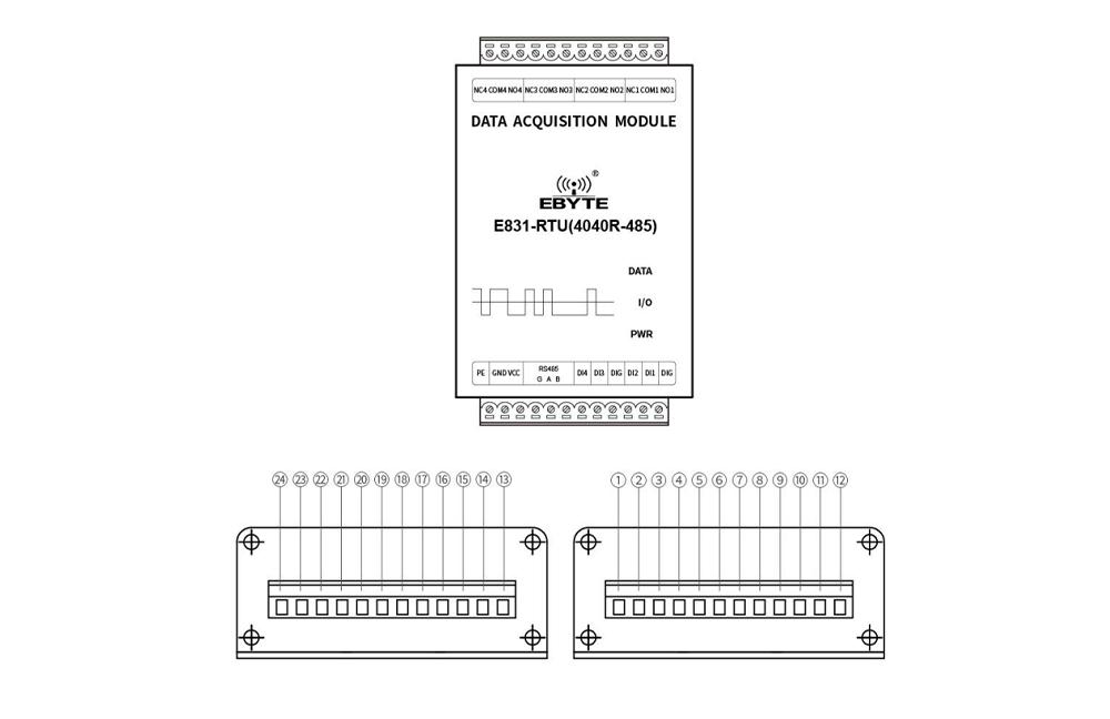
| No. | Ports and other definitions | Function | Description |
|---|---|---|---|
| 1 | PE | Connect with the earth | Connect with the earth |
| 2 | GND | Crimped power input negative | Power supply reference ground |
| 3 | VCC | Crimped power input positive | Power input, DC 8V ~ 28V, 12V / 24V recommended |
| 4 | RS485-G | RS485 signal reference ground | RS485 signal reference ground, it is recommended to connect |
| 5 | RS485-A | RS485 interface A | RS485 interface A is connected to device A interface |
| 6 | RS485-B | RS485 interface B | RS485 interface B is connected to device B interface |
| 7 | DI4 | Digital input channel 4 | Form dry contact with DIG |
| 8 | DI3 | Digital input channel 3 | Form dry contact with DIG |
| 9 | DIG | Digital input signal reference ground | Digital input signal reference ground, used with DI terminal |
| 10 | DI2 | Digital input channel 2 | Form dry contact with DIG |
| 11 | DI1 | Digital input channel 1 | Form dry contact with DIG |
| 12 | DIG | Digital input signal reference ground | Digital input signal reference ground, used with DI terminal |
| 13 | NO1 | Relay 1 normally open pin | Used with relay 1 common terminal |
| 14 | COM1 | Relay 1 common terminal | Used with relay 1 normally open pin / normally closed pin |
| 15 | NC1 | Relay 1 normally closed pin | Used with relay 1 common terminal |
| 16 | NO2 | Relay 2 normally open pin | Used with relay 2 common terminal |
| 17 | COM2 | Relay 2 common terminal | Used with relay 2 normally open pin / normally closed pin |
| 18 | NC2 | Relay 2 normally closed pin | Used with relay 2 common terminal |
| 19 | NO3 | Relay 3 normally open pin | Used with relay 3 common terminal |
| 20 | COM3 | Relay 3 common terminal | Used with relay 3 normally open pin / normally closed pin |
| 21 | NC3 | Relay 3 normally closed pin | Used with relay 3 common terminal |
| 22 | NO4 | Relay 4 normally open pin | Used with relay 4 common terminal |
| 23 | COM4 | Relay 4 common terminal | Used with relay 4 normally open pin / normally closed pin |
| 24 | NC4 | Relay 4 normally closed pin | Used with relay 4 common terminal |
| LED light | ||
|---|---|---|
| DATA | Serial data indication | Two-color light, green indicates data reception, blue indicates data transmission |
| I/O I | / O status indicator | Two-color light, any one input has a signal, green indicator is on, any one output has a signal, blue indicator is on, when there is both output and input, both lights are on at the same time, the indicator is cyan. |
| PWR | Power indicator | Red LED,Always on |