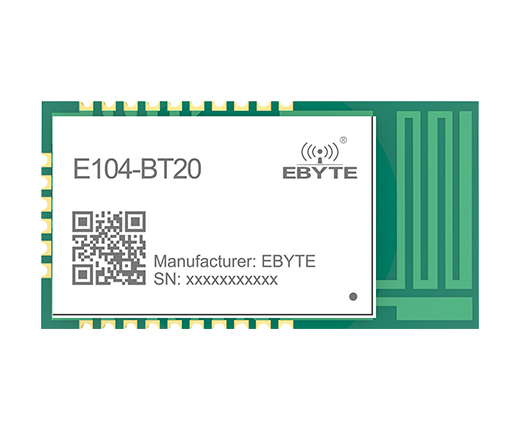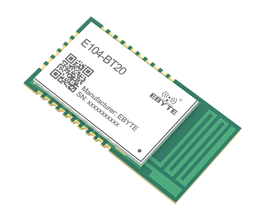

E104-BT20 Ebyte 2.4GHz ISM GFSK BR EDR2.1 UART wireless bluetooth transceiver bluetooth module
[IC]:RTL8760ATT
[Frequency]:2402~2480MHz
[Protocol]:V2.1
[Distance]:50m
[Size]:25*13mm
[Weight]:1.2±0.1g
[Introduction]:E104-BT20 Bluetooth serial communication module is a data transmission module based on Bluetooth Specification V2.1 BR / EDR Bluetooth protocol.The working frequency is 2.4GHz ISM, and the modulation method is GFSK. The module's maximum transmission power is 3dBm.
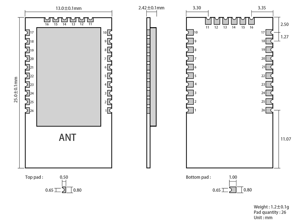
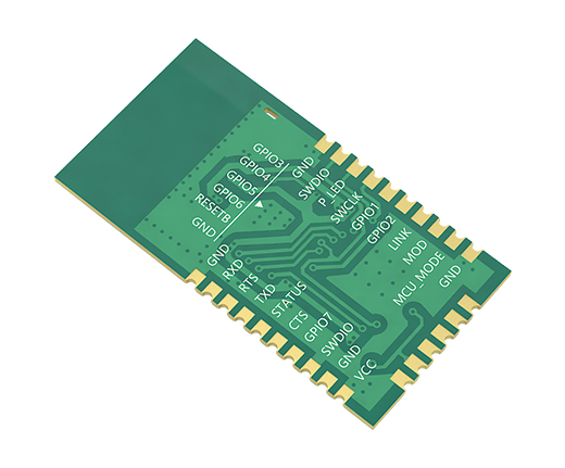
| No | Name | Direction | Function | Remark |
|---|---|---|---|---|
| 1 | GND | - | Power Supply Ground | Ground, connected to the power reference ground |
| 2 | SWDIO | Input/Output | - | Inputting and outputting data |
| 3 | P_LED | - | - | - |
| 4 | SWCLK | Input | - | Clock input |
| 5 | GPIO1 | Suspension | Universal IO | Pin for User configuration |
| 6 | GPIO2 | Suspension | Universal IO | Pin for User configuration |
| 7 | LINK | Output | LED indicator | Module connection indicator Output pin② |
| 8 | MOD | Input | modification | Input high level, the module enters configuration mode, input low level, the module enters transparent transmission mode |
| 9 | MCU_MODE | Input | - | (This pin has internal pull-down, and works in transparent transmission mode by default) |
| 10 | GND | - | Power Supply Ground | High level enters online programming mode, low level is working mode |
| 11 | GPIO3 | Suspension | Universal IO | Ground, connected to the power reference ground |
| 12 | GPIO4 | Suspension | Universal IO | Pin for User configuration |
| 13 | GPIO5 | Suspension | Universal IO | Pin for User configuration |
| 14 | GPIO6 | Suspension | Universal IO | Pin for User configuration |
| 15 | RESETB | Input | Module reset pin (RST) | Pin for User configuration |
| 16 | GND | - | Power Supply Ground | The low-level input module enters the hardware reset state, and the high-level input module returns to the normal working state. This function is used for reset operation in emergency |
| 17 | GND | - | Power Supply Ground | Ground, connected to the power reference ground |
| 18 | VCC | Input | 3.3V | Ground, connected to the power reference ground |
| 19 | GND | - | Power Supply Ground | Power Supply Input |
| 20 | GPIO7 | Suspension | Universal IO | Ground, connected to the power reference ground |
| 21 | CTS | Input | Hardware flow control | Pin for User configuration |
| 22 | STATUS | Output | LED indicator | UART clear transmit input pin |
| 23 | TXD | Output | TX Power Ground | Module status indicator Output pin① |
| 24 | RTS | Output | Hardware flow control | Module external output serial data |
| 25 | RXD | Input | RX Serial Port | UART request send input pin |
| 26 | GND | - | Power Supply Ground | Module receives external serial data |


